
Welcome, and thanks for reading. This page will provide a comprehensive overview of the feature set for the new Chaos Tank system implemented in the 2.0 update and how to configure new tanks, or customize existing ones.
This documentation is available in PDF format.
Please note: The 2.0 update is for UE5 only. While UE4 versions are in working order, due to the deprecation of physx, updates will no longer be maintained for older versions.
ADVANCED TANK BLUEPRINT - V2.0
(a guide on how to set up a new tank or modify an existing one)
- 1. MESHES
- 2. TEXTURES
- 3. MATERIALS
- 4. SKELETON SOCKETS
- 5. COLLISION
- 6. CHASSIS SETUP
- 7. WEAPONS
- 8. ANTENNAS
- 9. CAMOUFLAGES
- 10. CAMERA SETUP
- 11. PHYSICAL SETTINGS
- 12. POST PROCESS ANIMATIONS
1. MESHES

To introduce a new tank, the following components are essential. For each tank, you'll need:
• A skeletal mesh representing the tank. The structure of the skeleton in the 3D editor must closely resemble the skeleton structure in the project. This alignment is crucial as the engine employs a single common skeleton for all tanks. Deviations in the imported skeleton hierarchy compared to the project's skeleton can result in errors. Additionally, position the tank's center at the midpoint of the chassis along the X-axis. This placement facilitates adjustments to the center of mass.
• (Optional) - The skeletal mesh should incorporate linear tracks capable of move- ment through UV animation. If you're exclusively employing geometric tracks, the cre- ation of UV tracks can be omitted.
• A destroyed static mesh. This mesh becomes visible upon tank destruction.
• Static meshes for the tracks. As they're animated, these meshes will follow a spline path. The center of each track should be positioned accordingly.


To use only the UV tracks, there's no need to create geometric tracks.
2. TEXTURES

Every mesh necessitates a corresponding set of textures. The texture maps encompass:
• BC – Base color (+opacity in alpha channel if required)
• N – Normal map
• AORM – Ambient Occlusion, Roughness, Metallic
• E – Emissive (optional)
Additionally, in the case of adding camouflage, additional color textures are mandatory for each.


3. MATERIALS
In this context, individual materials are essential for each texture set belonging to the tank. Additionally, materials are required for the instances that will be presented upon tank destruction. All materials are structured as instances. To introduce a new tank, simply replicate the material from another tank and modify the Albedo, Normal, and AORM textures accordingly. You can also adjust the Emissive texture if applicable.

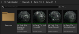

For each camouflage, you need to make a similar set of materials.

4. SKELETON SOCKETS
For each cannon of the tank, it is necessary to have sockets, which will determine the spawn point of the projectile.
The main cannon socket must be attached to the “main_gun” bone.


Machine gun bones should be attached to those bones responsible for the rotation of the machine gun.


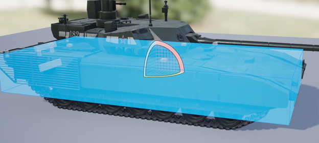
5. COLLISION
• Incorporate constraints for primitives to prevent any overlap during mesh simulation (e.g., restrict the gun's movement) and ensure realistic behavior.

- Occasionally, certain hulls might include components obstructing the gun's movement, like the rear sections of tanks such as the T-90. In these cases, it's crucial to incorporate collision primitives. A script is in place to autonomously detect obstacles obstructing the gun's path. If intersections occur between the gun and hull collision elements, the gun is adjusted upward.


6. CHASSIS SETUP
6.1. BASICS


At this stage, the tank should be driving.
6.2. SPLINE AND GEOMETRIC TRACKS ANIMATION


• AnimPointIndex – the index of the spline point to animate
• InteractWithWheel – if the point is above the wheel and can touch it. When the wheel moves up, the tracks will rise with the wheel, avoiding crossing.

• VibrationOccurrenceInvert – inverts the direction of movement in which the vibration should occur
• SaggingBack – maximum sag when driving backwards
• SaggingForward – maximum sag when driving forward

EXAMPLE: Spline and array setup example for the tank PZ5 Panther


6. Adjust the “TrackPath_R” position on the Y-axis.

6.3. UV TRACKS AND ANIMATION BLUEPRINT
Specify the "Tiling Segment Length". This variable dictates the pace at which the UV tracks move. It's essential that the value of this variable corresponds to the length of the track segment that repeats in the design. This ensures that the speed of movement remains accurate and synchronized with the visual representation of the tracks.


Generate the Animation Blueprint. It's advisable to duplicate the existing animation blueprint to avoid the need to recreate the code within the Event Graph. The animation graph is comprised of the following components:
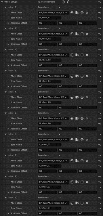
- Wheels Rotation: The initial component involves animating the wheels. Incorporate the necessary nodes for the wheels present in your tank's design. You can eliminate redundant nodes that might not be applicable to your tank's setup and integrate any missing nodes as required. Ensure a seamless connection with the relevant variables for accurate representation.

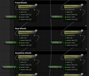

- Wheel Z Offset: This section pertains to the vertical movement of the wheels during suspension operation. It's responsible for animating the vertical displacement of the wheels as the suspension system reacts.The analogy is shown on the example below.


- Hydraulic Wheel Alignment: Typically, wheels don't merely move vertically; they follow an arc-like path. In addition to vertical movement, there's also a horizontal component. This block, manages the horizontal movement, ensuring that the wheels' motion accurately reflects this arc-like trajectory.


- Hydraulics: It is responsible for the movement of hydraulics. These are just “Look at” nodes with a wheel bone as the target.


- Next comes the block with the animation of sagging and vibration of the tracks. Here, in fact, the functionality of the “TankSplineAnim” array is repeated, only now for the UV tracks.


If "InteractWithWheel" is enabled, a clamp is added.


6.4. DRIVING WHEEL SYNCHRONIZATION
6.4.1a. for Geometric Tracks


6.4.1b. for UV Tracks
For UV tracks, synchronization variables are distinct. Parameters that prove effective for one system might not yield optimal results for the other. Customizing these variables independently ensures the best performance for each track system.
To correct the speed of rotation of the wheel when using UV tracks, use the variable “WheelSpeedCorrecionUV”.

The starting position of the wheel is controlled by variables “WheelStartingAngleUVR” and “WheelStartingAngleUVL”.

6.4.2. Speeding up the Synchronization Process
Values are selected by testing. To speed up the selection, additional logic has been created in the blueprint of the controller, which allows you to change these parameters during the game.


The process unfolds as follows: Upon game initiation, time dilation is activated by pressing the designated button (T). As the tank propels forward, the wheel's rotation speed becomes the focal point. Simultaneously, auxiliary logic is engaged to fine-tune this rotation speed until the desired effect is achieved. With each refinement, the variable's value is showcased through a Print String. The value at which the wheel aligns with the desired rotation speed is noted and set as the default. Following this, a parallel procedure is conducted for UV tracks, mirroring the approach taken with the wheels.
IMPORTANT: You can find a video that shows the process of selecting parameters for synchronization by clicking here.
The chassis animation is now configured and ready.
7. WEAPONS
Use the “BP_TankWeapon” component in the controller blueprint to set up guns.
![]()
In the array “Weapons”, create the number of elements corresponding to the number of weapons.

Inside each element of the array are the parameters of the guns (damage, accuracy, shell spawn socket, etc.), as well as the rotation speed of the turret on which the gun is installed.

You also need to set the rotation of all turrets and guns in the animation blueprint. The “TurretsRot” and “GunsRot” arrays contain the final calculated rotation values for each turret and gun. The rotation of the bones should be arranged according to the following schemes:


The indexes of arrays need to be matched. For example, the zero index in the array “Weapons” corresponds to the zero index in the arrays “TurretsRot” and “GunsRot”.
8. ANTENNAS
In the controller blueprint, establish an array of elements to match the number of antennas present on the tank. Each individual antenna should have its Oscillation Frequency, Stiffness, and Damping values specified.
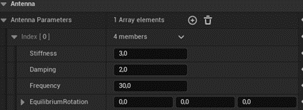
Setting up the antenna wobble physics can be configured inside the animation blueprint as shown below:

9. CAMOUFLAGES
In the blueprint of the controller, in the Camo array, create the number of elements corresponding to the number of camouflages.

In arrays “Material instance”, “Material instance destroyed”, “Material slot ID”, and “Material slot ID destroyed”, create the number of elements corresponding to the number of material slots. In the “Material slot ID” and “Material slot ID destroyed” arrays, specify the slot indices, and in the “Material instance” and “Material instance destroyed” arrays, specify the materials that should be in these slots.

10. CAMERA SETUP
The camera behavior can be customized by using the Zoom variables below:
- SniperCameraMaxZoom - maximum magnification of sight
- CameraZoomStep - camera zoom speed in arcade mode
- TargetArmLengthMax – maximum target arm length in arcade mode
- TargetArmLengthMin - minimal target arm length in arcade mode
- Socket offset sniper - adjusts the position of the camera in sniper mode

11. PHYSICAL SETTINGS
Physical settings remain consistent with standard Chaos wheeled vehicles, as the Vehicle Movement Component utilized is based on the Chaos Wheeled Vehicle Movement Component, with some additions.
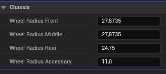
- You can adjust the physical wheel radius, damping, brake force, etc. in blueprint wheels, as in conventional wheeled vehicles.

- Among the pivotal parameters, the maximum torque stands out; its magnitude directly impacts the overall speed of the tank. A higher value accelerates the tank's movement as a whole.
- The torque curve also plays a big role. It shows the relationship between the revolutions per minute (RPM) of the tank engine and its torque. With its help, you can adjust the acceleration of the tank in different areas of engine speed.

- Another crucial factor is the gear ratios. A higher gear ratio results in slower tank movement within that gear, yet it enhances the tank's capability to conquer steeper inclines.

- To rotate instead of the steering wheel, the arcade rotation controller is used. The larger the Yaw Torque Scaling value, the faster the acceleration of the turn.

Several custom mechanics have also been added:
- Variable “ReverseTurnInReverse” - reverse of the turn when moving back
- Variable “MaxSpeedKMH” - Maximum linear speed limiter. If the speed is greater than this value, then the forward motion input will be reset to zero
- Variable “MaxTurningSpeed” - Maximum turn speed limit, deg/sec. If the angular velocity of the tank exceeds this value, then the Yaw input is set to zero
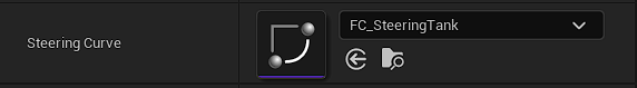
- Sreering Curve - Curve that establishes the relationship between the linear speed of the tank (x-axis) and the multiplier of the maximum turning speed (y-axis)
12. POST PROCESS ANIMATIONS
1. Create another physical asset for the skinned mesh.
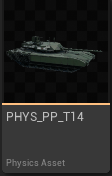
IMPORTANT: Once created, this asset will automatically become the default for the skeletal mesh.

We don't need it, returns the collision asset back.

2. Copy the animation blueprint of the post process from another tank.

3. In this blueprint, in the “Rigidbody” node, select the post process physical asset.


4. In the skeletal mesh setup, assign this animation blueprint as the post process.

5. In the post process physics asset, add a hull collision (and turret if it has animated parts), assign them a Kinematic physics type.
6. Add primitives to the bones you want to animate and set their physics type to Simulated.

7. If the constraints were not created automatically, then create them. Adjust the constraints.
